Alpha Industries, Inc. [781] 935-5150
∑ Fax [617] 824-4579 ∑ Email sales@alphaind.com ∑ www.alphaind.com
1
Specifications subject to change without notice. 6/00A
GaAs 50 dB IC Voltage Variable
Dual Control Attenuator DC≠3 GHz
Features
I Dual Control Voltages
I Low Insertion Loss
I 8 Lead Hermetic Surface Mount Package
I Capable of Meeting MIL-STD
Requirements
5
-11
AT002N5-11
Description
The AT002N5-11 is a GaAs IC FET absorptive
attenuator. This device provides up to 50 dB variable
attenuation from DC≠3 GHz. Attenuation can be
controlled by varying each of the two control bias voltages
from 0 to -5 V. This attenuator is recommended for fast
response AGC circuits in commercial and high reliability
applications.
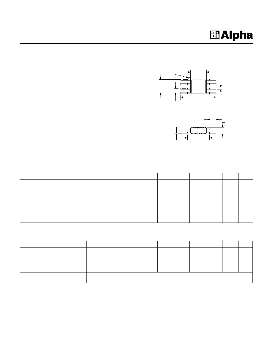
0.180 (4.57 mm)
SQ. MAX.
0.400 (10.16 mm)
0.380 (9.65 mm)
0.150
(3.81 mm)
0.050
(1.27 mm)
TYP.
ORIENTATION
MARK
0.017 (0.43 mm)
0.013 (0.33 mm)
0.006 (0.15 mm)
0.004 (0.10 mm)
0.250 (6.35 mm)
0.200 (5.08 mm)
0.070 (1.78 mm)
0.040 (1.02 mm)
0.075
(1.91 mm)
MAX.
Parameter
1
Frequency
4
Min.
Typ.
Max.
Unit
Insertion Loss
2
DC≠1.0 GHz
1.2
1.4
dB
DC≠2.0 GHz
1.4
1.8
dB
DC≠3.0 GHz
1.7
2.0
dB
Attenuation Range
DC≠1.0 GHz
50
52
dB
DC≠2.0 GHz
45
48
dB
DC≠3.0 GHz
40
42
dB
VSWR (I/O)
DC≠1.0 GHz
1.2:1
1.3:1
DC≠2.0 GHz
1.4:1
1.5:1
DC≠3.0 GHz
1.6:1
1.8:1
Electrical Specifications at 25∞C
1. All measurements made in a 50
system, unless otherwise specified.
2. Insertion loss changes by 0.003 dB/∞C.
3. Video feedthru measured with 1 ns risetime pulse and 500 MHz bandwidth.
4. DC = 300 kHz.
5. See Quality/Reliability section.
Parameter
Condition
Frequency
Min.
Typ.
Max.
Unit
Switching Characteristics
Rise, Fall (10/90% or 90/10% RF)
10
ns
On, Off (50% CTL to 90/10% RF)
15
ns
Video Feedthru
3
20
mV
Input Power for 1 dB Compression
For All Attenuation Levels
0.5≠3 GHz
0
dBm
0.05 GHz
-3
dBm
Control Voltages
V
Low
= 0 to -0.2 V @ 20
µA Max.
V
High
= -5 V @ 100
µA Max.
Operating Characteristics at 25∞C
GaAs 50 dB IC Voltage Variable Dual Control Attenuator DC≠3 GHz
AT002N5-11
2
Alpha Industries, Inc. [781] 935-5150
∑ Fax [617] 824-4579 ∑ Email sales@alphaind.com ∑ www.alphaind.com
Specifications subject to change without notice. 6/00A
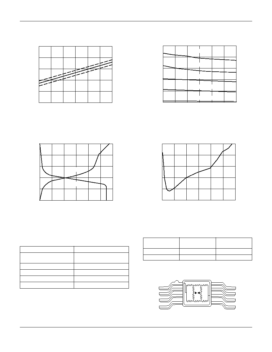
Insertion Loss vs. Frequency
Frequency (GHz)
0.4
DC
1
2
3
0.8
1.2
1.6
2.0
Inser
tion Loss (dB)
2.4
+85∞C
-55∞C
Attenuation (By State) vs. Frequency
Frequency (GHz)
10
DC
1
2
3
20
30
40
50
Atten
uation
(dB)
60
50 dB ± 4 dB
40 dB ± 2 dB
30 dB ± 1 dB
20 dB ± 0.5 dB
10 dB ± 0.2 dB
Relative Attenuation vs. Control Voltages
Relative Attenuation (dB)
-5.0
DC
20
10
30
50
40
60
-4.0
-3.0
-2.0
-1.0
V
1
V
2
Control V
oltages
(V)
0
V
1
(Series)
V
2
(Shunt)
F = 1 GHz, V
P
1
= 3.5 V
Typical Performance Data
Typical Transfer Curve
Pin Out
J
1
GND
V
1
V
2
GND
GND
GND
J
2
Attenuation vs. 1.0 dB Compression Point
Attenuation (dB)
-5
0
10
5
15
25
20
30
0
5
10
15
P
IN
at 1.0 dB Compression (dBm)
20
F = 500 MHz
1. V
P
= FET pinchoff voltage.
Characteristic
Value
RF Input Power (RF In)
10 mW > 500 MHz 0/-8 V Control
4 mW 50 MHz -8 V Control
Control Voltage (V
C
)
+0.2 V, -10 V
Operating Temperature (T
OP
)
-55∞C to +125∞C
Storage Temperature (T
ST
)
-65∞C to +150∞C
Thermal Resistance (
JC
)
25∞C/W
Absolute Maximum Ratings
Attenuation
V
1
V
2
J
1
≠J
2
0
-5
Insertion Loss
-5
0
Full Attenuation
Truth Table